


Chapter 9 Watchdog Timer
IX - 2
Overview
9-1 Overview
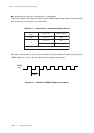
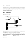
This LSI has a watchdog timer. This timer is used to detect software processing errors. It is controlled by
the watchdog timer control register (WDCTR). And, once an overflow of watchdog timer is generated, a
watchdog interrupt (WDIRQ) is generated. If the watchdog interrupt is generated twice, consecutively, it
is regarded to be an indication that the software cannot execute in the intended sequence; thus, a
system reset is initiated by the hardware.
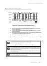
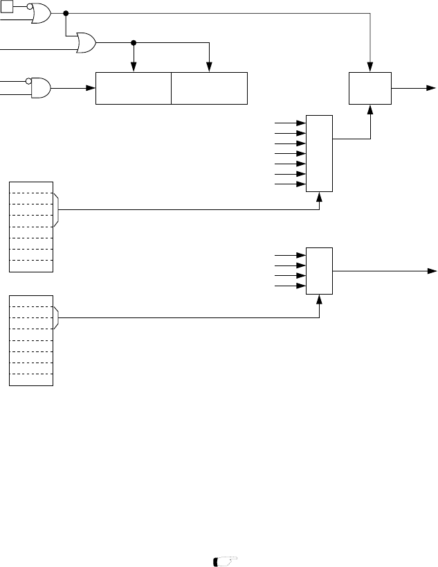
9-1-1 Block Diagram
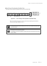
Watchdog Timer Block Diagram
Figure 9-1-1 Block Diagram (Watchdog Timer)
7
0
1/2
15
~1/2
20
R R
internal reset release
WDIRQ
S
1/2~1/2
14
R
MUX
fs/2
14
fs/2
12
fs/2
10
fs/2
8
fs/2
6
fs/2
4
fs/2
2
HALT
fs
(sysclk)
MUX
fs/2
20
fs/2
18
fs/2
22
fs/2
16
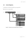
WDCTR
WDTS1
-
WDTC0
WDTC1
WDTC2
-
WDTS0
WDEN
7
0
DLYCTR
DLYS1
DLYS2
BUZS0
BUZS1
BUZS2
BUZOE
DLYS0
-
NRST
STOP
writeWDCTR
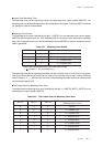
The watchdog timer is also used as a timer to count the oscillation stabilization wait time. This is used as
a watchdog timer except at recovering from STOP mode and at reset releasing.
The watchdog timer is initialized at reset or at STOP mode, and counts system clock (fs) as a clock
source from the initial value (x'0000'). The oscillation stabilization wait time is set by the oscillation
stabilization control register (DLYCTR). After the oscillation stabilization wait, counting is continued as a
watchdog timer.
[ Chapter 2 2-8. Reset ]