


VI - 43
Chapter 6 8-bit Timers
Remote Control Carrier Output
6-11 Remote Control Carrier Output
6-11-1 Operation
Carrier pulse for remote control can be generated.
Operation of Remote Control Carrier Output (Timer 0, Timer 5)
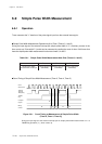
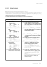
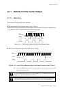
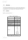
Remote control carrier pulse is based on output signal of timer 0 or timer 5. Duty cycle is selected from 1/
2, 1/3. RMOUT (P10/P11) outputs remote control carrier output signal.
Base
timer output
RMOUT
(1/3 duty)
RMOUT
(1/2 duty)
Base period set by timer
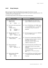
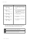
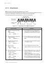
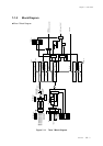
Count Timing of Remote Control Carrier Output (Timer 0, Timer 5)
(A) Even if the RMOEN flag is off when the carrier output is high, the carrier waveform is held
by the synchronizing circuit.
Figure 6-11-1 Duty Cycle of Remote Control Carrier Output Signal
Figure 6-11-2 Count Timing of Remote Control Carrier Output Function (Timer 0, Timer 5)
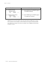
Before the RMOEN flag is switched to on, set the P1OMD0 flag or P1OMD1 flag of the P1OMD
register to "1". After it is switched to off, set it to "0".
When the RMOEN flag is changed, do not change the base cycle and its duty at the same
time. If they are changed at the same time, the carrier wave form is not output properly.
Base
timer output
RMOUT
(1/3 duty)
RMOEN
Output ON
Output OFF
(A)