


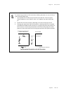


Setup Example
XVI - 7
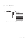
Chapter 16 D/A Converter
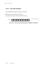
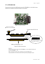
16-4 Setup Example
Channel fixed D/A Converter Setup Example
Conversion channel should be set to DA0.
An example setup procedure, with a description of each step is shown below.
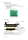
(1) Set the analog output pin (set at the procedure 2),
as the specfical function pin by the port A input
mode register (PAIMD). Also, set to "input mode"
by the port A I/O direction control register
(PADIR), and to "no pull-up resistance" by the
port A pull-up resistance control register
(PAPLUD).
(2) Set PA0 to D/A output pin by the DACH1-0 flag of
the D/A converter control register (DACTR).
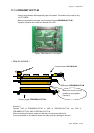
(3) Set the D/A conversion data by the D/A converter
input register01 (DADR01).
(4) Set the DABUSY flag of the D/A converter control
register (DACTR) to"1" to start the D/A
conversion. The result is output to the DA3-DA0.
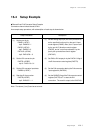
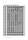
Setup Procedure
(1) Set the port A pin.
PAIMD (x'3F3C')
bp0 : PAIMD0 = 1
PADIR (x'3F3A')
bp0 : PADIR0 = 0
PAPLUD (x'3F4A')
bp0 : PAPLUD0 = 0
(2) Set the D/A conversion pin.
DACTR (x'3FBE')
bp1-0 : DACH1-0 = 01
(3) Set the D/A converter input data.
DADR01 (x'3FBF')
(4) Start thte D/A conversion.
DACTR (x'3FBE')
bp2 : DABUSY = 1
Description
Note : The above (1) to (2) can be set at once.