


Chapter 4 I/O Ports
IV - 6
Port 0
4-2 Port 0
General Port Setup
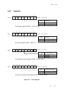
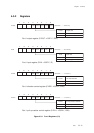
Each bit of the port 0 control I/O direction register (P0DIR) can be set individually to set each pin as input
or output. The control flag of the port 0 direction control register (P0DIR) should be set to "1" for output
mode, and "0" for input mode.
To read input data of pin, set the control flag of the port 0 direction control register (P0DIR) to "0" and
read the value of the port 0 input register (P0IN).
To output data to pin, set the control flag of the port 0 direction control register (P0DIR) to "1" and write
the value of the port 0 output register (P0OUT).
Each bit can be set individually whether pull-up resistor is added or not, by the port 0 pull-up resistor control
register (P0PLU). Set the control flag of the port 0 pull-up resistor control register (P0PLU) to "1" to add pull-
up resistor.
Special Function Pin Setup
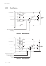
P00 to P02 are used as I/O pin for serial interface 0, as well. P00 is output pin of the serial interface 1
transmission data. The SC1SBOS flag of the serial interface 1 mode register 1 (SC1MD1) is set to "1" for
serial data output. P01 is the input pin of the serial interface 1 reception data. P02 is I/O pin of the serial
interface 1 clock. The SC1SBTS flag of serial interface 1 mode register 1 (SC1MD1) is set to "1" for serial
clock output.
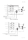
P03 to P05 are used as I/O pin for serial interface 0, as well. P03 is output pin of the serial interface 0
transmission data. The SC0SBOS flag of the serial interface 0 mode register 1 (SC0MD1) is set to "1" for
serial data output. P04 is the serial interface 0 reception data input pin. P05 is I/O pin of the serial interface
0 clock. The SC0SBTS flag of serial interface 0 mode register 1 (SC0MD1) is set to "1" for serial clock
output pin.
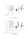
P01 to P02 are used as I/O pin for serial interface 4, as well. P01 is data I/O pin of the serial interface 4. The
SELI2C flag of the serial interface 4 address register 1 (SC4AD1) is set to "1" for serial data output pin. P02
is the serial interface 4 clock I/O pin. The SELI2C flag of serial interface 4 address register 1 (SC4AD1) is
set to "1" for serial clock I/O.
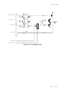
P06 is used as buzzer output pin, as well. When the bp7 of the oscillation stabilization control register
(DLYCTR) is "1", buzzer output is enabled.
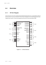
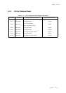
4-2-1 Description