


VI - 33
Chapter 6 8-bit Timers
Serial Transfer Clock Output
6-8 Serial Interface Transfer Clock Output
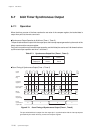
6-8-1 Operation
Serial interface transfer clock can be created by using the timer output signal.
Serial InterfaceTransfer Clock Operation by 8-bit Timer (Timers 4 and 5)
Timer 4 output can be used as a transfer clock source for serial interface 1. Timer 5 output can be used as
a transfer clock source for serial interface 0.
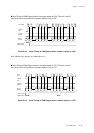
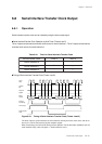
Timing of Serial Interface Transfer Clock (Timers 4 and 5)
N
00 01 N-1
N
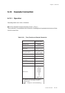
Count
clock
TMnEN
flag
Compare
register
Binary
counter
Interrupt
request flag
00 01 00N-1
N
00 01 N-1
N
Timer output
Serial transfer
clock
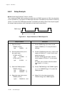
The timer output is synchronized to the serial transfer clock by the timer count clock, and its fre-
quency is 1/2 of the set frequency by the compare register.
Other count timings are same to the timing of timer operation. For the baud rate calculation and the
serial interface setup, refer to chapter 11. Serial Interface 0 and 1.
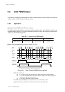
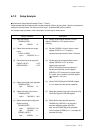
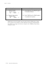
Table 6-8-1 Timer for Serial Interface Transfer Clock
Figure 6-8-1 Timing of Serial Interface Transfer Clock (Timers 4 and 5)
Serial transfer clock
Timer 4 Ti mer 5
Serial interface 0 -
√
Serial interface 1
√
-
Serial interface 3 -
√