


XVIII - 17
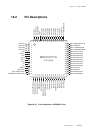
Chapter 18 Flash EEPROM
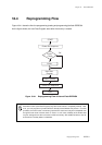
Onboard Serial Interface Programming Mode
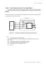
Use of PanaX serial writer (DWIRE programming)
xYou need not to write load program in advance and also be able to use all space of the Flash
EEPROM as user program area.
xVPP pin must supply 5.0 V from external power source.
xP53 and P54 pins should be reserved as dedicated pins for serial writer to prevent other
user circuits on the target board from communicating with the device. Alternatively, design your
target board on which the serial writer can program the device correctly.
xConnect pull-up resistors on the target board to P53 and P54 pins, which are connected to the
power supply.
xNRST and SBT2 pins are output from the serial writer through an open connection.
xInstall a switch on the target board to toggle between NRST for serial programming and NRST for
normal opeation. Alternatively, install a wired-OR connection. (For a wired-OR connection,
disable NRST for normal operation during serial programming)
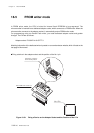
xYou can connect a serial writer easily by setting a 10-wire flat cable on the target board. If a 10-
wire flat cable cannot be mounted to the target board, you can solder it directly.
xThe signal wire lenghth from the serial writer connector to the microcontroller (NRST, P53 and
P54) must be shorter than 15 cm.
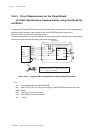
Selection of circuit device on the target board.
xLoad capacity of reset signal (NRST)
Use the oscillation stabilization wait time right after reset in DWIRE programming. That is, rising
time from reset must be shorter than 1/3 of the oscillation stabilization wait time.
Set as:
Maximun load capacity of reset signal ≤ the value derived from following formula and 100 µF
Oscillation stabilization wait time
3 X Pull-up resistor value
xPull-up resistor value (P53, P54)
Caluculate the resistor value using following formula. When operating voltage is 3.3 V, appropri-
ate value is over 1.65 kΩ.
Operating voltage (VDD)
Maximum output current of pin (IOL)
CRST =
RupMin =