


Chapter 7 16-bit Timer
VII - 6
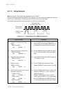
Control Registers
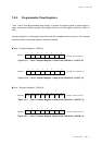
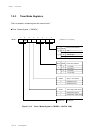
Figure 7-2-5 Timer 7 Preset Register 1 Lower 8 bits (TM7PR1L : x'03F74', R/W)
Timer 7 Preset Register 1 (TM7PR1)
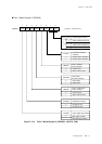
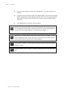
Figure 7-2-6 Timer 7 Preset Register 1 Upper 8 bits (TM7PR1H : x'03F75', R/W)
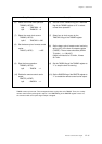
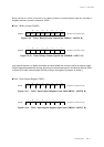
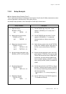
Figure 7-2-7 Timer 7 Preset Register 2 Lower 8 bits (TM7PR2L : x'03F7C', R/W)
Timer 7 Preset Register 2 (TM7PR2)
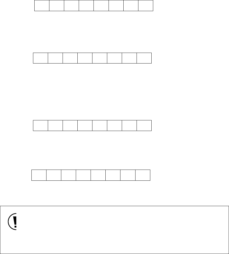
Figure 7-2-8 Timer 7 Preset Register 2 Upper 8 bits (TM7PR2H : x'03F7D', R/W)
The timer 7 preset register 1 and 2 are buffer registers of the timer 7 compare register 1 and 2. If the set
value is written to the timer 7 preset register 1 and 2 when the counting is stopped, the same set value is
loaded to the timer 7 compare register 1 and 2. If the set value is written to the timer 7 preset register 1
and 2 when the counting is operated, the set value of the timer 7 preset register 1 and 2 is loaded to the
timer 7 compare register 1 and 2 at the timing that the timer 7 binary counter is cleared.
76543210
( At reset : X X X X X X X X )
TM7PR1L
TM7PR1L7 TM7PR1L6 TM7PR1L5 TM7PR1L4 TM7PR1L3 TM7PR1L2 TM7PR1L1 TM7PR1L0
76543210
( At reset : X X X X X X X X )
TM7PR1H
TM7PR1H7 TM7PR1H6 TM7PR1H5 TM7PR1H4 TM7PR1H3 TM7PR1H2 TM7PR1H1 TM7PR1H0
76543210
( At reset : X X X X X X X X )
TM7PR2L
TM7PR2L7 TM7PR2L6 TM7PR2L5 TM7PR2L4 TM7PR2L3 TM7PR2L2 TM7PR2L1 TM7PR2L0
76543210
( At reset : X X X X X X X X )
TM7PR2H
TM7PR2H7 TM7PR2H6 TM7PR2H5 TM7PR2H4 TM7PR2H3 TM7PR2H2 TM7PR2H1 TM7PR2H0
When data load timing from 16-bit timer preset register to compare register matches to write
timing to preset register with instruction, correct value may not be loaded to the compare
register. Therefore, write to preset register should be done while timer is stopped or within
timer interrupt processing.
And use MOVW instruction for write to preset register.