


Chapter 1 Overview
I - 6
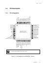
Hardware Functions
Watchdog timer
- Watchdog timer frequency can be selected from fs/2
16
, fs/2
18
or fs/2
20
.
Remote control output
Based on the timer 0, and timer 3 output, a remote control carrier with duty
cycle of 1/2 or 1/3 can be output.
Synchronous output
Timer synchronous output, Interrupt synchronous output
- Port 6 outputs the latched data, on the event timing of the synchronous
output signal of timer 1, 5, or 7, or of the external interrupt 2 (IRQ 2).
Buzzer output Output frequency can be selected from fosc/2
9
, fosc/2
10
, fosc/2
11
,
fosc/2
12
, fosc/2
13
, fosc/2
14
, fx/2
3
, fx/2
4
.
Automatic transfer controller (ATC)
Data in the whole memory space (256 KB) can be transferred.
- External interrupt start / internal event start / software start
- Max. 255 bytes continuous transfer
- Support serial interface sequence transmission / reception
- Burst transfer ( interrupt shutdown is built-in )
A/D converter 10 bits X 7 channels input
D/A converter 8 bits X 2 channels input
Serial interface 4 types
Serial interface 0 (Full-Duplex UART / Synchronous serial interface )
❑ Synchronous serial interface
- Transfer clock source
fosc/2, fosc/4, fosx/16, fosc/64, fs/2, fs/4
1/2 of UART baud rate timer ( timer 5 ) output
- MSB/LSB can be selected as the first bit to be transferred. Any
transfer size from 1 to 8 bits can be selected.
- Sequence transmission, sequence reception or both are available.
❑ Full-Duplex UART ( Baud rate timer : Timer 5 )
- Parity check, Overrun error, Framing error detection
- Transfer size 7 to 8 bits can be selected.
[Note : When Matsushita standard serial writer is used for flash memory
version, serial interface 0 is used for program transfer.]