


Nokia Network Voyager for IPSO 4.0 Reference Guide 133
Transparent Mode Processing Details
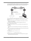
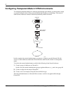
When you configure transparent mode, it is added to the IPSO kernel as a module situated
between the layer 2 and the upper protocol layers. When a logical interface is configured for the
transparent mode, transparent mode Address Resolution Protocols (ARP) and IP receive
handlers replace the common ARP and IP receive handlers. This enables the transparent mode
operation to essentially intercept all packets between the link layer (layer 2) and IPv4 and IPv6
network layer (layer 3).
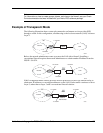
Besides transmitting packets that are bridged from one interface to another based on MAC
addresses, the transparent mode module also transmits packets that originate locally or are
forwarded based on routing. Locally originated ARP packets are broadcast on all interfaces of
the transparent mode group. Locally originated IP packets are also broadcast on all interfaces of
the transparent mode group if the egress interface is not found in the forwarding table.
If there are any VLAN interfaces among the interfaces in the transparent mode group, the link
header of a bridged packet is modified to have the proper format for the egress interface.
Neighbor learning is the process of associating a MAC address with an interface whenever a
packet is received with an unknown source MAC address. This association is called a neighbor
control block. The neighbor control block is deleted from the address table after a period of
inactivity (age time out). The age time-out is reset to this initial value for the neighbor control
block on receiving any packet from that neighbor.
Packet processing for a firewall consists of ingress and egress processing. This applies only to IP
packets; ARP packets are never delivered to the firewall. Egress processing occurs when a
packet returns from the firewall’s ingress filtering, the packet is delivered to the firewall again
for egress filtering. The packet is delivered with the interface index of the egress interface. If it is
a link multicast packet, a copy of the packet is made for each interface of the transparent mode
group, except the received interface. It is then delivered to the firewall with the associated
interface index.
Note
Network Address Translation (NAT) is not supported in transparent mode. Transparent
mode does support implicit “NATing” of the packet’s destination IP address to a local IP
address to deliver packets to the security server on the local protocol stack. It does this by
performing a route lookup for the packet’s destination IP address to determine whether the
packet destination is local after the packet returns from the firewall’s ingress filtering. If the
packets destination is local, the packet is delivered to the IP layer for local processing.