


2
76 Nokia Network Voyager for IPSO 4.0 Reference Guide
7. Click Apply.
A new logical interface appears in the Interface column. The new interface is on by default.
You can add more ATM logical interfaces by repeating this action.
8. Click the logical interface name in the Interface column of the Logical Interfaces table to go
to the Logical Interface page.
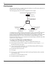
9. Enter the IP address for the local end of the PVC in the Local Address text box.
10. Enter the IP address of the remote end of the PVC in the Remote Address text box.
Click Apply.
11. Enter a number in the IP MTU text box to configure the device’s maximum length (in bytes)
of IP packets transmitted in this interface. Click Apply.
The default value is 1500.
Note
The maximum packet size must match the MTU of the link partner.
12. (Optional) Change the interfaces logical name to a more meaningful name by typing the
preferred name in the Logical Name text box.
13. Click Apply.
14. (Optional) Add a comment to further define the logical interfaces function in the Comments
text box.
15. Click Apply.
16. Click Save to make your changes permanent.
To change the VPI/VCI of an ATM interface
Note
To move an IP address from one PVC to another, you must first delete the logical interface
for the old PVC, then create a new logical interface for the new PVC.
1. Click Interfaces under Configuration > Interface Configuration in the tree view.
2. Click the physical interface link to configure in the Physical column.
Example:
atm-s2p1
3. Find the ATM logical interface you wish to remove in the Logical Interfaces table and click
the corresponding Delete button.
4. Click Apply.
The logical interface disappears from the list. Any IP addresses configured on this interface
are also removed.
5. Select the VPI/VCI range in the VPI/VCI Range Configuration selection box.