


5
208 Nokia Network Voyager for IPSO 4.0 Reference Guide
You can create IP clusters by combining flash-based platforms other than the IP2250 with disk-
based or different flash-based models. For example, the following combinations are valid:
flash-based IP1260, disk-based IP1260, IP380
two flash-based IP1260 platforms
IP385, IP380, IP265
This list provides examples only. There are many other combinations that you can use to create
clusters.
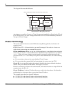
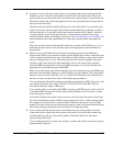
Example Cluster
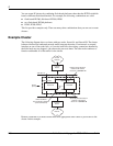
The following diagram shows a cluster with two nodes, firewall A and firewall B. The cluster
balances inbound and outbound network traffic between the nodes. If an internal or external
interface on one of the nodes fails, or if a node itself fails, the existing connections handled by
the failed node are not dropped—the other node processes them. The other node continues to
function and handle all of the traffic for the cluster.
Routers connected to an IPSO cluster must have appropriate static routes to pass traffic to the
cluster. In this example:
Internet
Firewall A Firewall B
192.168.1.0
192.168.2.0
Secondary Cluster Protocol
Network: 192.168.4.0
Cluster IP: 192.168.4.10
Cluster
(ID 10)
External
Router
Primary Cluster Protocol
Network:192.168.3.0
Cluster IP: 192.168.3.10
192.168.1.10192.168.1.10
192.168.2.10 192.168.2.10
VPN-1/FireWall-1
Synchronization Network
(Secured Network)
Internal
Router
Internal
Network