


2
32 Nokia Network Voyager for IPSO 4.0 Reference Guide
For example, the logical interface of a physical interface
eth-s2p1
is called
eth-s2p1c0
. The
logical interfaces for PVCs 17 and 24 on an ATM NIC in slot 3 are called
atm-s3p1c17
and
atm-s3p1c24
respectively.
Once a logical interface exists for a device, you can assign an IP address to it. For Ethernet,
FDDI, and Token Ring, you must specify the interface's local IP address and the length (in bits)
of the subnet mask for the subnet to which the device connects.
If you are running multiple subnets on the same physical network, you can configure additional
addresses and subnet masks on the single logical interface connected to that network. You do not
need to create additional logical interfaces to run multiple subnets on a single physical network.
For point-to-point media, such as ATM, serial, or HSSI, you can either assign IP addresses or
configure an unnumbered interface. When assigning IP addresses you must specify the IP
address of the local interface and the IP address of the remote system's point-to-point interface.
You can add only one local/destination IP address pair to a point-to-point logical interface. To
assign IP addresses to multiple VCs, you must create a logical interface for each VC. IP subnets
are not supported on point-to-point interfaces.
Whenever an unnumbered interface generates a packet, it uses the address of the interface that
the user has specified as the source address of the IP packet. Thus, for a router to have an
unnumbered interface, it must have at least one IP address assigned to it. The Nokia
implementation of unnumbered interfaces does not support virtual links.
Note
If you make changes to IP addresses or delete interfaces, the firewall sometimes does not
learn of the changes when you get the topology. If you get the topology and your changes to
interfaces are not shown, stop and restart the firewall.
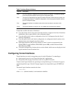
Interface Status
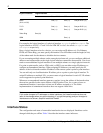
The configuration and status of removable-interface devices are displayed. Interfaces can be
changed while they are offline. Table 2 describes the interface status indicators.
Serial
(X.21 or V.35)
One (
c0
)One (
c0
) One per DLCI (
c#
)
T1/E1 One (
c0
)One (
c0
) One per DLCI (
c#
)
HSSI One (
c0
)One (
c0
) One per DLCI (
c#
)
Token Ring One (c0)
ISDN One (
c#
)
Physical Interface Logical Interface
Default Cisco HDLC PPP Frame Relay