


Nokia Network Voyager for IPSO 4.0 Reference Guide 185
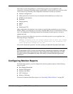
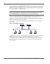
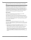
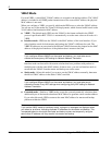
Figure 2 VRRP Configuration with Internal and External VRIDs
In this example, Platform A acts as the master for both VRID 1 and VRID 2 while Platform B
acts as the backup for both VRID 1 and VRID 2.
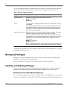
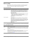
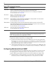
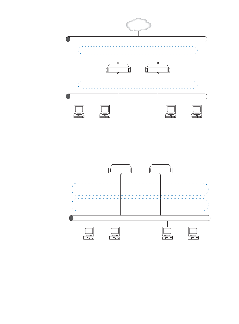
You can configure several platforms to be part of multiple VRIDs while they simultaneously
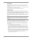
back up each other, as shown in Figure 3. This is known as an active-active configuration.
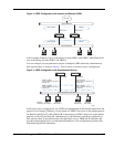
Figure 3 VRRP Configuration with Simultaneous Backup
In this active-active configuration, two VRIDs are implemented on the internal network for the
purpose of load sharing. Platform A is the master for VRID 5 and serves as the default gateway
for Host H1 and Host H2, while Platform B is the master for VRID 7 and serves as the default
gateway for Host H3 and Host H4. Simultaneously, both Platform A and B are configured to
back up each other. If one platform fails, the other takes over its VRID and IP addresses and
provides uninterrupted service to both default IP addresses. This configuration provides both
load balancing and full redundancy.
Internet
00497
VRID 2 Master
Backup
200.10.10.1 200.10.10.2
192.168.2.1 192.168.2.2
VRID 1 Master
Backup
Platform A Platform B
Internal Network
Public Network
VRID 5 (master)
backup address: 192.168.2.5
priority: 254
VRID 7 (master)
backup address: 192.168.2.7
priority: 254
VRID 7 (backup)
backup address: 192.168.2.7
priority: 253
VRID 5 (backup)
backup address: 192.168.2.5
priority: 253
192.168.2.1 192.168.2.2
00498
Host H1
192.168.2.5
Host H2
192.168.2.5
Host H3
192.168.2.7
Host H4
192.168.2.7
Default
Gateway:
Platform A Platform B
Internal Network 192.168.2.0