


5
246 Nokia Network Voyager for IPSO 4.0 Reference Guide
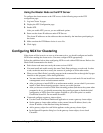
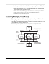
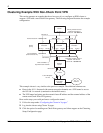
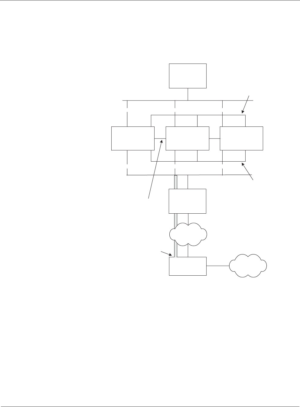
Clustering Example With Non-Check Point VPN
This section presents an example that shows how easy it is to configure an IPSO cluster to
support a VPN with a non-Check Point gateway. The following diagram illustrates the example
configuration:
This example cluster is very similar to the previous example. The additional elements are:
Hosts in the 10.1.1.0 network (the remote encryption domain) use a VPN tunnel to access
the 192.168.1.x network (connected to the internal router).
The VPN tunnel end points are the external cluster IP address and the external address of the
remote non-Check Point VPN gateway.
Here are the steps you would perform to configure the tunnel:
1. Follow the steps under “Configuring the Cluster in Voyager.”
2. Log into the cluster using Cluster Voyager.
3. Click the option for enabling non-Check Point gateway and client support on the Clustering
Setup Configuration page.
192.168.1.0
192.168.2.0
Secondary Cluster Protocol
Network: 192.168.4.0
Cluster IP: 192.168.4.10
Cluster
(ID 10)
Primary Cluster Protocol
Network:192.168.3.0
Cluster IP: 192.168.3.10
.1 .1
.1 .1
Firewall B
eth-s1p1
eth-s2p1
eth-s3p1
eth-s4p1
Firewall C
eth-s1p1
eth-s2p1
eth-s3p1
eth-s4p1
.2
.2 .2
.2
.3 .3
.3 .3
Firewall A
eth-s1p1 eth-s3p1
eth-s4p1eth-s2p1
Internal Cluster IP
192.168.2.5
Internal
Router
192.168.1.5
Non-Check
Point VPN
Gateway
VPN Tunnel
Tunnel Endpoint
(External Cluster IP)
Tunnel Endpoint:
10.1.2.5
External
Router
Internet
192.168.2.5
10.1.1.0
Network
192.168.2.10 192.168.2.10 192.168.2.10
192.168.1.10 192.168.1.10 192.168.1.10
VPN-1/FireWall-1
Synchronization Network