


Nokia Network Voyager for IPSO 4.0 Reference Guide 135
Note
For information on how to create groups, objects, and rules on the firewall, see your Check
Point documentation that was included with your Nokia IPSO software package.
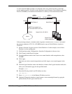
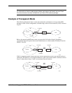
Example of Transparent Mode
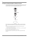
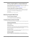
The following illustration shows a network connected to an Internet service provider (ISP)
through a switch. In this configuration, all addressing to the local area network (LAN) is done at
Layer 2.
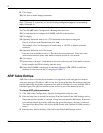
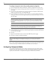
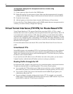
Below, the network administrator wants to protect the LAN with a firewall. Installing a
conventional firewall requires the network administrator to obtain another IP address from the
ISP, IP 1.5.4.0/24.
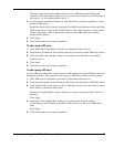
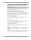
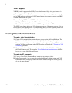
Nokia’s transparent mode solution provides firewall protection for the LAN without having to
obtain new IP addresses or reconfigure addresses on the LAN. Packet traffic continues to run at
Layer 2, rather than at Layer 3 with a conventional firewall solution.
LAN
Internet
ISP
Switch
1.5.2.1/24
00293
1.5.3.2/24
LAN
Internet
ISP
SwitchSwitch
1.5.3.2/24
1.5.3.3/24
1.5.4.0/24
00294
LAN
Internet
ISP
SwitchSwitch
1.5.3.2/24
1.5.3.3/24
1.5.3.4/24
00295
Nokia
Platform
with Firewall